Behavioral box design
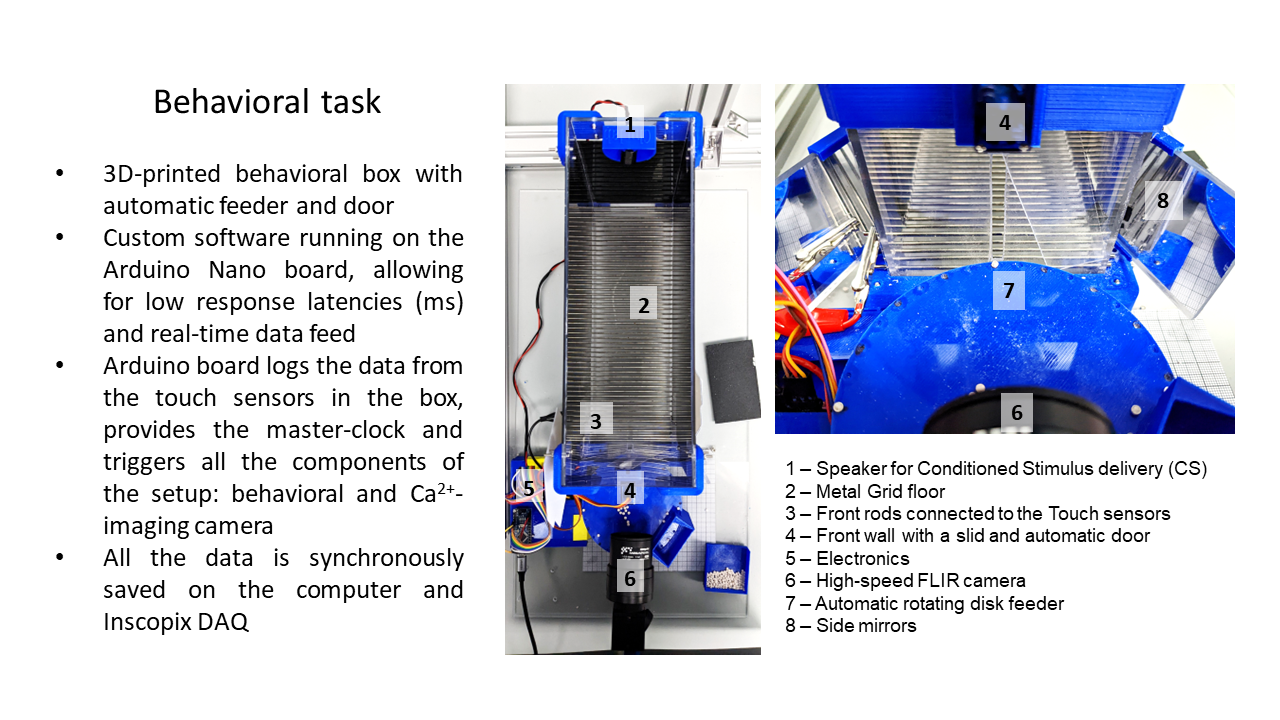
Current protocol is performed with the use of in-house manufactured behavioral box system, which consists of multiple components:
- Plexiglas chamber with a metal bar floor and a slit in the front wall, housing the mouse during the experiment;
- Motorized feeder system for precisely delivering and positioning single pellets (5-10 mg Sucrose Tap Pellets, TestDiet) in front of the slit;
- Arduino-based controller autonomously performing the programmed experimental protocol (written in C++), interfacing with the touch sensors in the box and providing the master clock signal;
- Single FLIR 1.6MP High-Speed camera (Model: Blackfly S BFS-U3-16S2M) with a system of mirrors, saving the video stream on the computer with the use of a Python interface.
Hence, there are 4 main components that you will need to assemble the behavioral box:
- Plexiglas sheets cut to size and drilled
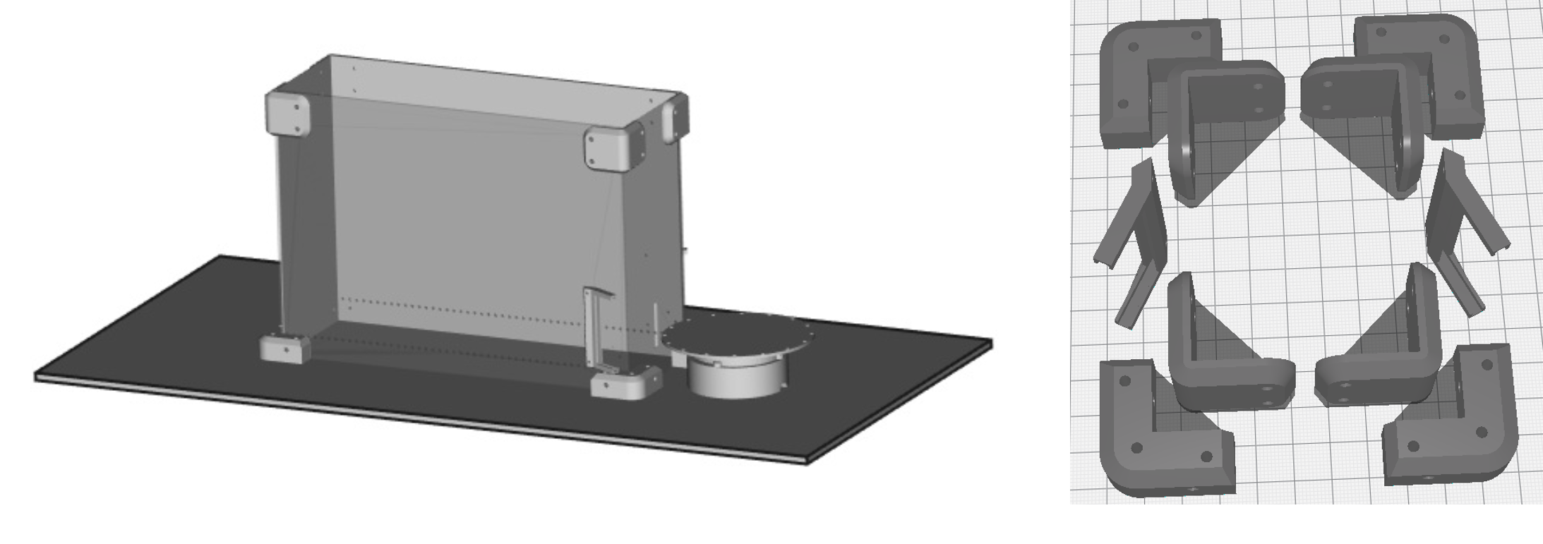
- 3d printed parts for the box such as corners holding the sheets together,
- 3d printed feeder and Arduino components
- Small screws and nuts kit to put everything together and metal rods for the floor (can be ordered from Amazon)
All of them can be purchased or manufactured in house with the use of 3d printer and CNC machines or just ordered online.
3D printing the parts

.stl files for printing the components are provided in this folder of the repository. Dimensions for the parts and schematics is provided in supplementary materials of the repository and the article. Computer-aided design (CAD) software along with CNC cutter machine can be used to scale and speed up the manufacturing process (all the design files provided were made using FreeCAD software), but the original design can be easily reproduced without it using only all-manual tools.
Q&A
If you still have questions after reading this and the article please let us know and we list it in this section.
